KineBody Pro Instructions:
(last updated 221204)
Exporting & Importing Poses
Overview
With the Export/Import Poses feature, you can write pose data to, and read from, an editable text file. This capability is designed as a way to use KineBody Pro pose data in an external application, or to introduce pose data from an external source into KineBody Pro.
A KineBody Pro ‘exported poses’ file contains numeric values representing 1 or more poses, including body position & orientation (6 degrees of freedom (DOF) total), plus euler angles for joint rotations, for all joints & their active degrees of freedom. It also provides ‘descriptor’ strings to indicate joint & DOF names, to assist you in locating specific joint data. The pose file doesn’t include fixed joint parameters, such as range of motion, position or orientation of the joint axes, & euler ‘sequence’.
Note also that this type of file is different from a KineBody Pro Repository file, which also contains pose information, but may also contain animation data. Repository files are intended only for backup and re-use with KineBody Pro - not for editing or transfer to other software systems.
For exported pose files, you can select from either of 2 sign conventions for joint angles:
Anatomical system: maintains consistent sign for similar movement names, & L-R symmetry, across all joints. For example, flexion is positive for all joints, regardless of whether the moving bone (viewed laterally) moves CW or CCW; similarly, abduction is positive whether applied to right or left.
Right-hand system: A global coordinate system defines positive rotations by the Right Hand Rule, and joint rotations are derived from these by matching the the joint rotation axis to the nearest global coordinate axis. Thus, for example, any joint rotation having a vertical or nearly vertical axis (e.g., internal/external rotation of humerus, femur, or tibia) will be considered positive when moving counter-clockwise, when viewed from above.
Further information about these sign conventions is provided below. The content & format of the export/import file is described in the lower part of this page.
Instructions
Locate controls: Controls for exporting & importing pose data are located in the ‘Delete, Export, Import’ section at the bottom of the Save & Restore panel.
The section includes a ‘multiple-select’ menu at the top, and buttons to Delete* or Export poses selected using that menu. Next to the Export button is a textbox, where you can enter a filename for the export file. The Import button, at the bottom, works independently of the multiple select menu. [The menu in the yellow section is only intended for selecting poses for Delete or Export operations – Note that there’s another menu just above, labeled ‘View a stored pose’, which contains an identical list of stored poses, but it’s only used for viewing the poses.]
Export poses: Before you can export a pose, it must first be named & saved into the KineBody repository. Instructions for these operations are provided here: Saving Poses (also accessible via the Help menu, under ‘More Instructions’).
To export poses, select the poses by name from the menu in the yellow section. You can select 1 or more poses to export – use the Shift or Ctrl keys to help select multiple poses. Next, you can optionally change the name of the export file, by entering a new name into the box to the right of the Export button. If you're using the Webapp edition, the exported poses file will be saved to your browser’s ‘Downloads’ folder (pls see your browser documentation if you wish to change that location). If you're using the Android edition, the file is saved to the '/KineBody' folder. (Please see Saving KineBody Pro Files to Android, for important information).
You select the sign system when you press the Export button, as follows:
> 'Normal' press: selects Anatomical signs (where possible, see below).
> [Ctrl]-press: selects RH signs (for all DOFs).
After you press the Export button, a confirmation message in green font will appear briefly, below the button: "Poses exported to <path & filename>".
Modify poses: You can manually modify exported poses, using any text editor. If the file was generated by KineBody Pro, it will include joint and DOF (degree of freedom) names to help you locate the desired values.
If necessary, use the KineBody Pro app to determine (or confirm) the names of the joints and DOFs. Joint names in the export file match those listed in the ‘Moving joint’ menu (within the Move subpanel).
For Webapp users: You can also determine the joint name in the ‘Pointing at’ box, by hovering the cursor over the segment distal to the joint and pressing the [Ctrl] and [Alt] keys.
To determine the DOF names, inspect the joint sliders that appear when you select a joint: the DOF names on the joint sliders are identical to those in the export file. You can correlate DOFs with rotation axes by color: the color bar atop each joint slider matches the rotation axis color as it appears in the viewing area.
When changing angle data, take care to check which sign system is being used: it's specified in the ‘Signs: ...’ field, at the end of the export file. For export files generated by KineBody Pro, the 'Signs' field provides a brief description of the sign system. If the file was generated by any other source, it may be abbreviated to 2 characters: 'An' for anatomical, 'RH' for right handed. If the RH system is used, you can also check the ‘sign suffix’ value ( ±1 ) for each DOF you plan to modify: values of -1 indicate that the RH directions are listed in the DOF name in 'positive/negative' order, i.e., opposite to the those of the anatomical directions.
For example, the desriptor string for the left glenohumeral joint is
            " 16 gleno-humeral (L): [extension/flexion,int/external rotation,adduction/abduction ]*[-1,1,1]"
            .
The sign suffix contains a -1 in the left-most position, indicating that the
corresponding DOF name 'extension/flexion' describes the movements in 'positive/negative' order:
extension is positive, flexion is negative. By contrast, the 2nd DOF 'int/external rotation' has a
corresponding sign suffix of 1, meaning that internal rotation is negative, external is positive.
You can create a new pose file using data from some other source, by creating & using a custom-built application to do the conversion. In both cases, you must maintain the format of the pose data, in the following regards:
- Don’t add or remove any square brackets or commas, anywhere in the file. (These are essential for defining a legal JSON data structure, which is used to simplify the code for importing data).
- Don’t add digits to any numeric values, if they’re shown at full precision (15-17 decimal places). This will mess up the JSON import. On the other hand, it's acceptable to edit down to fewer digits, e.g., you can write "0.005" instead of "0.004999999999999893".
- Don’t remove any joints, to shorten the list. (The input routine assigns the angle data to joints by their position in the list, not by joint name or number).
- Be sure to include a file format version number (currently 'v02') at the start of the file, just before the 1st '['.
- Include either "Signs: An" or "Signs: RH" at the bottom of the file, to indicate which sign system to use.
If you’re building your own converter app, you can simplify the process somewhat, by omitting or reducing some of the pre-defined text content, as follows:
- The opening header (‘ This is an editable …unchanged !’ ) and appendix (‘Units…’) can be omitted entirely. Don’t remove the string ‘v01’ (possibly with different digits) !
- The descriptors (joint & DOF names, & joint numbers (2-110)) and time stamp (‘180901 120000’) can be replaced by empty strings (“”) (i.e., keep the double quotes intact).
Import poses: To import poses: Click the Import button, which opens a dialog box to request a filename & its location. After you select the file, the import is automatic: you don’t need to do any further steps, although it's a good idea to confirm that the poses were correctly added to the Repository: just check at the bottom of the ‘Select pose(s):’ menu for new names.
Note that each imported pose is given a new numeric suffix (‘-xxx’), which is appended to the posename listed in the file (FFI: see Saving Poses). If the posename in the file already has a 3 digit suffix, that suffix will not be replaced upon import. Instead, you’ll get a posename with 2 suffixes, which may be useful if you’re trying to track the processing history of a pose. You can avoid having multiple suffixes by removing the old ones while editing the pose file.
Also: when importing pose data, the sign system (Anatomical or RH) is defined within the pose file. The signs of the angles are automatically adjusted as necessary before the pose is saved to the repository. (Note: the automated conversions require that the file version string (‘v02’ or ‘v01’) be present in the file. If this string is missing, an error will show, and the data will not be imported.)
Details: Axes & Signs for Body Position & Orientation
Body position: refers to the location a point fixed within the ribcage (thorax unit), near its center; you can observe its location as the intersection of the blue, red, and green body axes. Coordinates (horizontal, vertical, & distance) are defined relative to the screen, with positive directions as follows:
horizontal is positive to the right.
vertical is positive upward.
distance is positive away from the viewer.
Notes:
The zero reference for body position (i.e., the origin of the coordinate system) lies at the center of the KineBody Pro viewing area, and the distance is zero at the screen.
Note that the signs match those of the KineBody Pro sliders for horizontal, vertical, and distance: these provide a quick way to check the polarities, without need to consult this documentation.
All body position coordinates are subject to the perspective effect: for example, as the body distance increases, a fixed horizontal position of 1m appears to be a smaller fraction of the viewing area width.
Body orientation: is defined as the 3D rotation of the ribcage (thorax), about the body origin and relative to the red, blue, and green axes as follows:
Spin is the rotation about the blue (longitudinal) axis, which is fixed to the body, and spatially normal to the green (tilt) axis.
Tilt is the rotation about the green axis, which lies parallel to the plane of the screen, but can change direction within that plane, as the dial angle is varied.
Dial is the rotation about an axis coming out of the screen.
Notes:
Signs for these angles are most readily discerned directly from the KineBody Pro app: from the initial ‘anatomical position’, dial is positive counterclockwise, spin is positive to the viewer’s right, tilt is positive ‘upward’ (the latter two implying displacement of a point anterior to the body origin, e.g., on the sternum).
At large angles, the angle values & signs can become confusing, owing to the KineBody Pro 'casual mode' feature: each body position can be described by two different sets of angles. The angle values and signs are simply related, but note the relation is not merely a change in sign. This is covered further in the next section.
It may seem feasible to discern the signs of the rotation angles using the Right Hand rule. This approach won't work well, however, because a) the axes don’t have clear markings re: which end is positive, and b) the tilt angle sign is related to horizontal axis direction using a Left Hand relation. You could work around these, with some trouble, i.e., manually track where the originally positive direction moved in space, and remember to flip the sign for tilt. However, it’s much simpler to just use the KineBody Pro app to discern the signs: e.g. if you have an image of a posed body and want to discern the signs of the rotation angles, simply rotate the ribcage to the same 'attitude', then read the correct angle values and signs from the body sliders.
Casual mode: is a KineBody Pro feature that allows full & free body rotations without limits on the tilt angle (at ±90°), and without abrupt jumps in the spin & dial values, when tilt exceeds the ±90° range. As such, the range for all three of these body angles is ±180°. Although this approach makes for simpler body movement, it comes with a downside: the body orientation at any time is associated with two different sets of 3 angles. For example, the figure below left shows an isolated ribcage with body angles of [40, 120, 50] for spin, tilt, & dial (resp). The figure below right shows the exact same orientation, alternatively represented by the triple [-140, 60, -130 ].
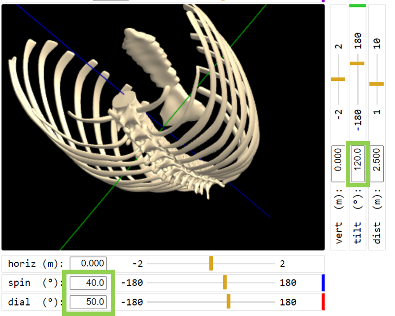
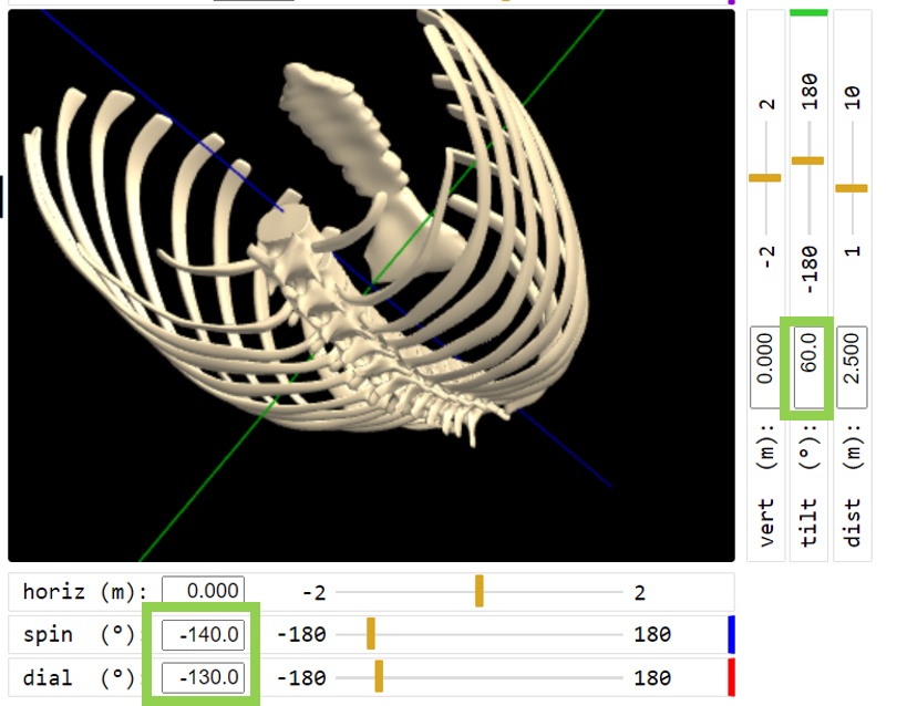
For the following discussion, it will be helpful to denote these two different angle sets as follows:
Principal values: When the tilt angle is in the range ±90° (the left figure above)
Extended values: When the tilt angle is outside the ±90° range (i.e., 90 to 180, or -90 to -180 ). (the right figure)
Note that the term ‘principal’ or ‘extended’ applies to the set of three angle values, i.e., they’re all principal or all extended; it doesn’t make sense to mix principal & extended values in any single specification of body orientation.
If you’re trying to correlate KineBody Pro angles with some non-KineBody data, it may be helpful to convert extended values to principal values. This can be accomplished by some simple relations:
(For tilt in the range of ±90° , no conversion is needed: the values are already principal).
For tilt outside the range ±90° , the angles can be converted via:
| principal tilt | = 180° - extended tilt |
| principal dial | = extended dial + 180° |
| principal spin | = extended spin + 180° |
Details: Sign Conventions for Joint Rotations
This section provides additional detail about the two possible sign systems for joints (Anatomical v. Right-Handed (RH)) available when you export poses.
Right-Handed System: In this convention, the signs for rotations are derived from a global coordinate system as shown below:
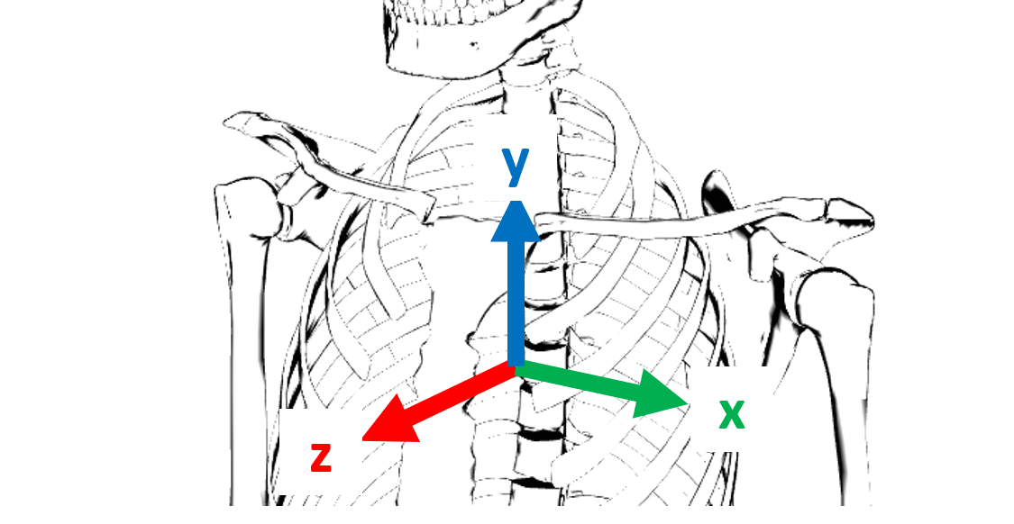
These axes have positive directions as follows: x positive to the right, y positive upward, and z positive toward the viewer. Important: this system of x,y, & z axes is only intended for defining the joint rotation signs - in particular, it does NOT define the positive direction for body displacements.
Signed rotations about these axes can be defined by the Right Hand Rule: if you imagine grasping the axis with your right hand, with your thumb pointing in the positive axis direction, your fingers will point in the positive rotation direction. The resulting positive rotation directions are shown in the next figure:
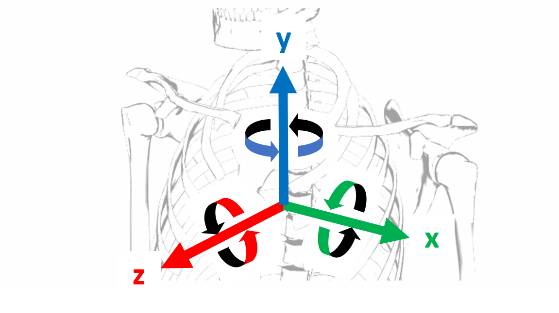
The rotation axes for each joint (shown by magenta, yellow, and cyan lines) are usually aligned to a greater or lesser degree with these global axes, when the body is posed in its ‘home’ position (body facing forward, upright). As such, the positive direction for each joint rotation axis is defined as the positive rotation direction for the most closely aligned global axis.
For example, the right gleno-humeral joint has 3 rotation axes: extension/flexion about the magenta axis, adduction/abduction about the yellow axis, and internal/external rotation about the cyan axis. In the home position, the gleno-humeral joint axes are not aligned with the global axes, as you can see from a birdseye view of the joint:
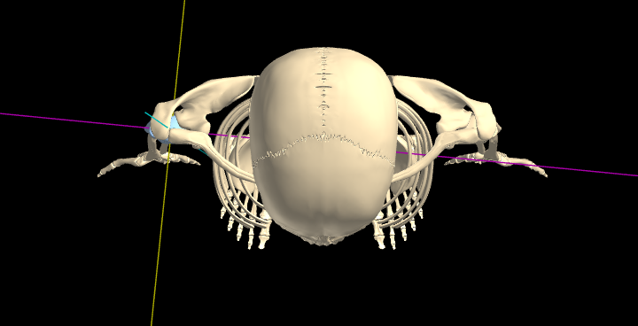
However, the magenta axis is most closely aligned with x, cyan with y, and yellow with z. So, those associations will define the positive rotation directions, i.e., for the magenta axis, positive rotation occurs when the distal end of the bone moves posteriorly, i.e., an extension movement. By similar logic, the positive direction for rotations about the yellow axis is adduction, and for the cyan axis, internal rotation is positive (Figure below, left). [Note: these relations apply specifically to the right gleno-humeral joint].
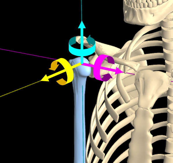
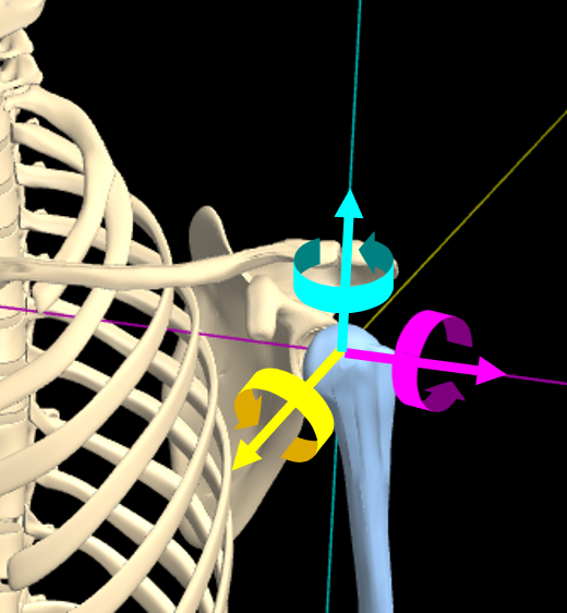
The positive rotation directions are identical for the left gleno-humeral joint, as they are derived likewise from the global xyz coordinates (see Figure above, right). Note, however, that this means the positive directions aren't symmetrical, in an anatomical sense, for the yellow and cyan axes: for the left glenohumeral joint, abduction and external rotation are positive. (But extension is still positive for rotations about the magenta axis).
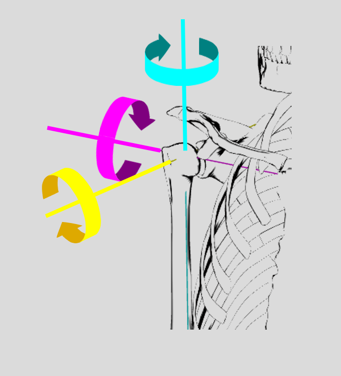
Anatomical sign system: Although the signs used in the Right-Handed system are consistent throughout the body, this can sometimes cause confusion: for example, 'abduction' is regarded as positive at the right shoulder, but negative at the left shoulder. Or, flexion is taken to be negative for cervical joints, but positive for lumbar joints. To bypass these situations, the Export/Import feature offers an 'Anatomical' sign system, to represent anatomical movements of the same name with the same sign, wherever feasible, e.g., abduction is positive regardless of left or right side. For example, the gleno-humeral joint positive directions in the Anatomical system are shown below:
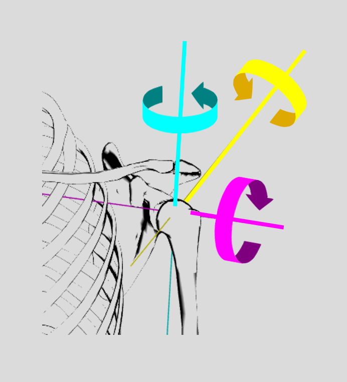
Anatomical signs are used not only for exporting & importing poses, but also for all the joint movement sliders. This gives you a way to verify the directions for any anatomical movement, i.e., values appearing on the sliders are Anatomical.
When the anatomical sign system is used, the positive direction is included in the 'descriptor'
string for each joint, in the exported pose file. For example: the descriptor string for
gleno-humeral (L) is:
" 16 gleno-humeral (L): [extension/flexion,int/external rotation,adduction/abduction ]".
When the DOF names include movement terms separated by a ‘/’, such as ‘extension/flexion’, the
directions are ordered as ‘negative / positive’, so in this example, extension is regarded as
negative, flexion as positive.
You may notice that some of the DOF names don't use two slash-separated names; for example, ‘axial rotation’or ‘lateral flexion’. In these cases, there is no special anatomical sign convention; rather, positive & negative directions are taken from the Right Hand sign system. Thus for example, ‘axial rotation’ is typically defined for rotations about a vertical (y) axis; then, positive rotation is counterclockwise when viewed from above (or equivalently, the anterior aspect of the associated bone(s) moves to the right).
At this point, it's important to clarify that, when you select RH signs for the export file, you're selecting to use that system for all the joint DOFs in the file. By contrast, when you select the Anatomical signs, you're selecting to use that convention wherever possible, but it doesn't apply to all DOFs !! Rather, some of the DOFs will use the RH convention, as it's the only one available. In short, you should regard the choice of Anatomical system as an abbreviation, for 'Anatomical signs, wherever possible, otherwise RH signs'.
Pose files exported using the RH system contain additional information in the joint & DOF name
string, to help clarify the signs. Following the DOF names is a ‘sign suffix’ string, such as ‘*[
-1,1,1 ]’. The 3 values are associated with the 3 DOFnames, respectively, and indicate that the
movement names are ordered as ‘negative/ positive’ (for entries = 1) or ‘positive/negative’ (for
-1). For example: if the pose file entry for gleno-humeral (L) is:
               [-35 ,0, 25]," 16 gleno-humeral (L): [extension/flexion,int/external
            rotation,adduction/abduction ]*[-1,1,1]
then the extension/flexion value has an associated sign suffix of -1, meaning that extension is
regarded as positive. Thus, the value (-35) represents 35° of flexion. By contrast, the
adduction/abduction value (25°) has an associated suffix of 1, meaning that abduction is positive:
In this case, the joint shows 25° of abduction.
Pose files exported using the Anatomical system do not contain sign suffix strings; in this case, the movement names are ordered ‘negative/positive’ throughout the file.
Pose File Format
A KineBody Pro pose file contains numeric values representing 1 or more KineBody poses, for body position & orientation (6 DOF tot), plus euler angles for joint rotations, for all joints & their active degrees of freedom, plus descriptor strings to indicate joint & DOF names
(A pose file doesn’t include: joint parameters, such as range of motion, position or orientation of the joint axes, or euler configuration)
A pose file is formatted as plain text, structured in a ‘JSON’ format, as a series of nested arrays. Content within the JSON/nested arrays is as follows:
[ // start of top level array
[ // start of data for 1st pose
[ posename, timestamp] ,
[ // start of section for body position & orientation data
[ [ horiz, vert, dist ] , descriptor string ] ,
[ [ spin, tilt, dial ] , descriptor string ]
] , // end of body position & orientation data
[ // start section of joint angle data: (the θ's represent generic angles; the DOF names indicate which is which).
[ [ θ1 , θ2 , θ3 ], descriptor string ] , // data for 1 joint, 1 to 3 DOF
[ [ θ1 , θ2 , θ3 ], descriptor string ] , // data for 2nd joint, 1 to 3 DOF
…
[ [ θ1 , θ2 , θ3 ], descriptor string ] // exactly 109 jts total
] // end joint angle data
] , // end of data for 1st pose
[ data for 2nd pose ] ,
…
[ data for last pose ] // any number of poses (subject to repository size limits)
] // end of top level array
Notes:
1) Descriptor strings: all numeric triples are followed by a string, describing:
- the joint name
- 1-3 DOF (degee of freedom) names
- (for 'Signs: RH' pose files only) a 3 element sign suffix array, with values of ±1. The array is enclosed in '[ ]' and separated from the DOF names by an asterisk .
2) Blank DOF names represent unused DOFs: e.g. [ a, , b] represents a joint with just 2 DOF. Note! the numeric angle value for any unused DOF should be left = 0.
3) Units: angles in degrees, lengths in meters.
4) Axes, References, and Signs: Please see the sections above, for body position & orientation and joints.
5) The selected sign system is saved into the exported file, in the string ‘Signs: Anatomical …’ or ‘Signs: RH…’ If this field is missing, the sign system defaults to ‘Anatomical’. For generating a pose file programmatically, it’s sufficient to include just the 1st two letters: ‘Signs: RH’ or ‘Signs: An’.
6) Interphalangeal joints, distinguishing hand v finger : An uppercase 'H' or 'F' is included in the joint name's suffix, following the regular 'L' or 'R' body side parameter, e.g., " 54 distal interphalangeal 3 (LH): ..." is a hand joint.
Note: in some (older) versions of the export files, the 'H' or 'F' characters are omitted, and as a result these joint names are the same for hand & foot. To distinguish between them, use the joint 'number' preceding the joint name:
- #41-56 ≡ hand
- #83-100 ≡ foot
e.g., " 54 distal interphalangeal 3 (L): ..." is a hand joint.
7) Neck & lumbar spine joints: In each of these sections, one joint cannot be moved independently.
In the neck, you cannot move the Occiput-C1 joint, because the control mechanism for that joint
has been redirected to handle movement of the entire neck. This is evident in the joint names:
3 neck (Occ-C1, C1C2, ..., C7T1) // all
neck joints, not just Occ-C1
4 C1C2 (atlanto-axial)
5 C2C3
The same holds for L5S1 in the lumbar spine.